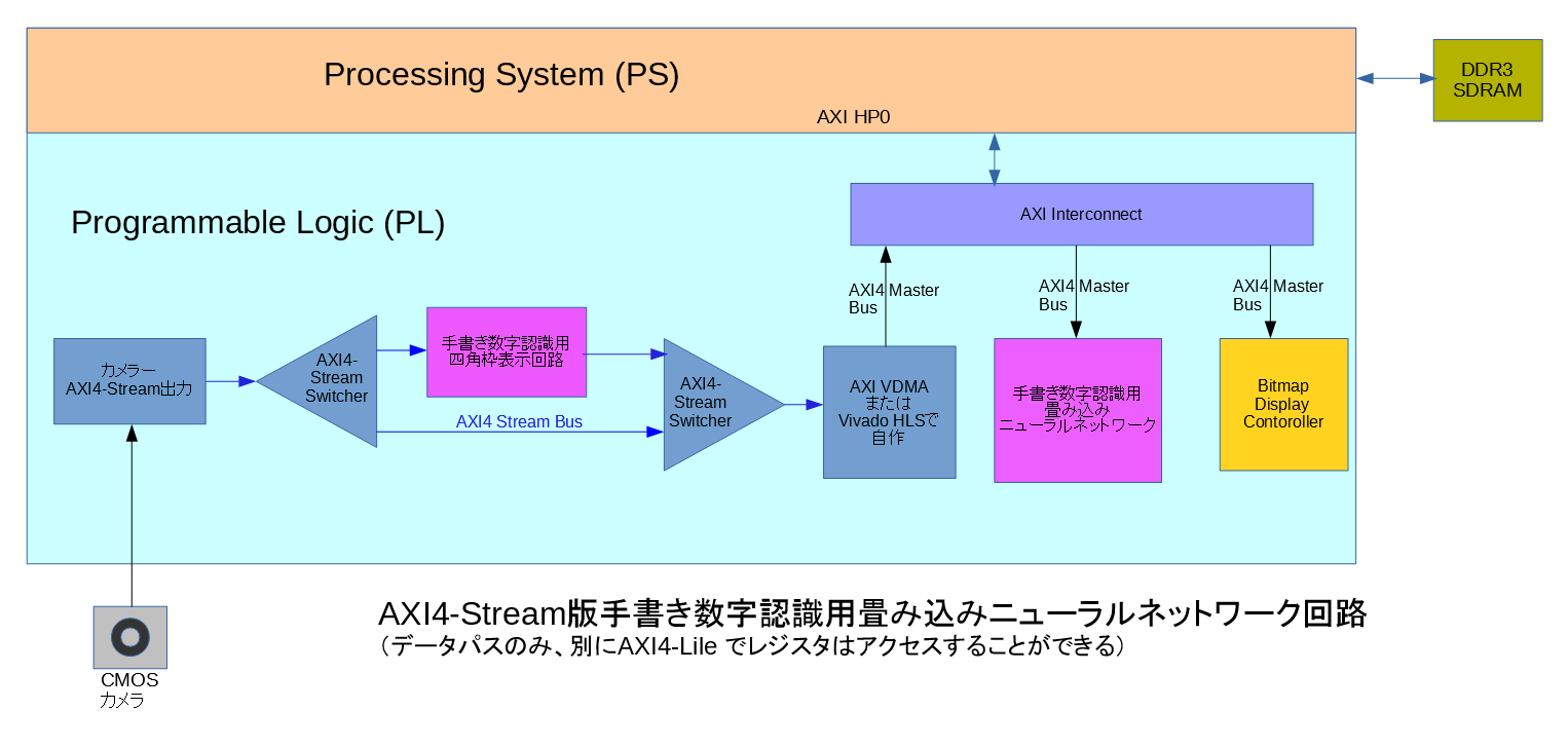
前回は、カメラで撮影した画像から手書き数字を指定し、手書き数字認識用畳み込みニューラルネットワークを使用して認識する回路の概要を解説した。今回は、そのパーツとなる手書き数字認識用四角枠表示回路をVivado HLS を使用して作ってみよう。
手書き数字認識用四角枠表示回路は、ある一定の幅と高さのピンクの枠を画像に追加するIP となっている。入出力はAXI4-Stream で、引数はAXI4-Lile でレジスタにマップされている。
ヘッダファイルの square_frame_gen.h を示す。
// square_frame_gen.h
// 2017/06/28 by marsee
//
#ifndef __SQUARE_FRAME_GEN_H__
#define __SQUARE_FRAME_GEN_H__
#define HORIZONTAL_PIXEL_WIDTH 800
#define VERTICAL_PIXEL_WIDTH 600
#define ALL_PIXEL_VALUE (HORIZONTAL_PIXEL_WIDTH*VERTICAL_PIXEL_WIDTH)
#endif
ソースコードのsquare_frame_gen.cpp を示す。
// square_frame_gen.cpp
// 2017/06/28 by marsee
//
#include <ap_int.h>
#include <hls_stream.h>
#include <ap_axi_sdata.h>
#include "square_frame_gen.h"
// AXI4-Streamで流れてきた画像に1ピクセルの幅の四角い枠を書く
// x_pos : 四角枠の内側の左上のx位置
// y_pos : 四角枠の内側の左上のy位置
// width : 四角枠内側のピクセルの幅
// height : 四角枠内側のピクセルの高さ
// off_on : 四角枠OFF - 0, ON - 1
int square_frame_gen(hls::stream<ap_axis<32,1,1,1> >& ins,
hls::stream<ap_axis<32,1,1,1> >& outs,
int x_pos, int y_pos, int width, int height, int off_on){
#pragma HLS INTERFACE s_axilite port=off_on
#pragma HLS INTERFACE s_axilite port=width
#pragma HLS INTERFACE s_axilite port=x_pos
#pragma HLS INTERFACE s_axilite port=height
#pragma HLS INTERFACE s_axilite port=y_pos
#pragma HLS INTERFACE s_axilite port=return
#pragma HLS INTERFACE axis register both port=outs
#pragma HLS INTERFACE axis register both port=ins
ap_axis<32,1,1,1> pix;
int gray_pix, val, i, j, x, y;
do {
#pragma HLS LOOP_TRIPCOUNT min=1 max=1 avg=1
// user が 1になった時にフレームがスタートする
ins >> pix;
} while(pix.user == 0);
for (y=0; y<VERTICAL_PIXEL_WIDTH; y++){
for (x=0; x<HORIZONTAL_PIXEL_WIDTH; x++){
#pragma HLS PIPELINE II=1
if (!(x==0 && y==0)) // 最初の入力はすでに入力されている
ins >> pix; // AXI4-Stream からの入力
if (off_on){
if (y==y_pos-1 && x>=x_pos-1 && x<=(x_pos+width+1)) // 上の枠線
pix.data = (0xff << 16)+0xff; // R = 0xff, B = 0xff, pink
else if (y>=y_pos-1 && y<=y_pos+height+1 && (x==x_pos-1 || x==x_pos+width+1)) // 横枠線
pix.data = (0xff << 16)+0xff; // R = 0xff, B = 0xff, pink
else if (y==y_pos+width+1 && x>=x_pos-1 && x<=(x_pos+width+1)) // 下の枠線
pix.data = (0xff << 16)+0xff; // R = 0xff, B = 0xff, pink
}
outs << pix;
}
}
return(0);
}
Vivado HLS 2016.4 で square_frame_gen プロジェクトを作った。

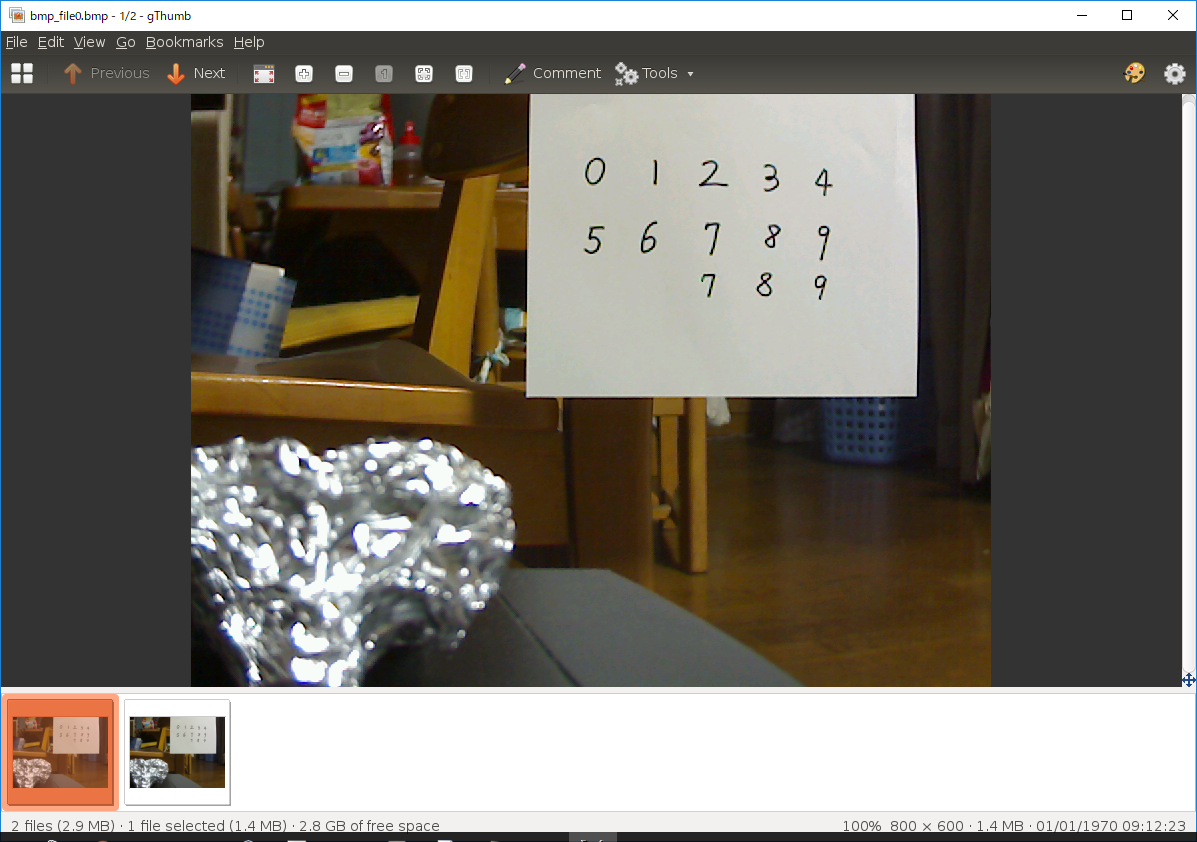
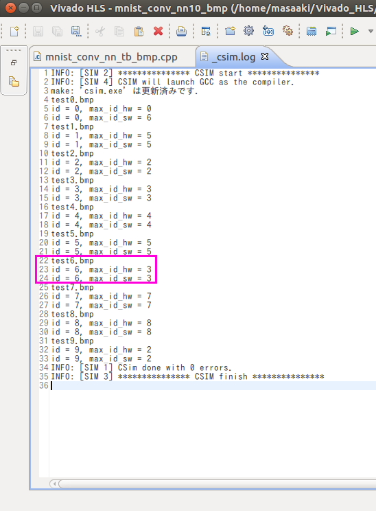
C シミュレーションを行った。

画像の真ん中を指定したので、四角枠線が書かれている。中のサイズは 28 x 28 ピクセルだ。

C コードの合成を行った。結果を示す。

レイテンシは 480005 クロックで、画像サイズは 800 x 600 = 480000 なので、ほぼ1クロックで 1 ピクセルの処理が行えることになる。
AXI4-Lile でのレジスタ・マップを貼っておく。
//------------------------Address Info-------------------
// 0x00 : Control signals
// bit 0 - ap_start (Read/Write/COH)
// bit 1 - ap_done (Read/COR)
// bit 2 - ap_idle (Read)
// bit 3 - ap_ready (Read)
// bit 7 - auto_restart (Read/Write)
// others - reserved
// 0x04 : Global Interrupt Enable Register
// bit 0 - Global Interrupt Enable (Read/Write)
// others - reserved
// 0x08 : IP Interrupt Enable Register (Read/Write)
// bit 0 - Channel 0 (ap_done)
// bit 1 - Channel 1 (ap_ready)
// others - reserved
// 0x0c : IP Interrupt Status Register (Read/TOW)
// bit 0 - Channel 0 (ap_done)
// bit 1 - Channel 1 (ap_ready)
// others - reserved
// 0x10 : Data signal of ap_return
// bit 31~0 - ap_return[31:0] (Read)
// 0x18 : Data signal of x_pos
// bit 31~0 - x_pos[31:0] (Read/Write)
// 0x1c : reserved
// 0x20 : Data signal of y_pos
// bit 31~0 - y_pos[31:0] (Read/Write)
// 0x24 : reserved
// 0x28 : Data signal of width
// bit 31~0 - width[31:0] (Read/Write)
// 0x2c : reserved
// 0x30 : Data signal of height
// bit 31~0 - height[31:0] (Read/Write)
// 0x34 : reserved
// 0x38 : Data signal of off_on
// bit 31~0 - off_on[31:0] (Read/Write)
// 0x3c : reserved
// (SC = Self Clear, COR = Clear on Read, TOW = Toggle on Write, COH = Clear on Handshake)
次に、C/RTL協調シミュレーションを行った。

C/RTL協調シミュレーション波形を示す。まずは全体の波形。

最初のAXI4-Lile でのレジスタ設定時の波形を貼っておく。

WDATA は10進数にしてある。x_pos に400、y_pos に 300 、四角枠の幅と高さに 28 を設定するのが分かると思う。
Export RTL を行った。

インプリメントしてもタイミングは満たされているようだ。
最後に、テストベンチのsquare_frame_gen_tb.cpp を貼っておく。
// square_frame_gen_tb.cpp
// 2017/06/28 by marsee
//
#include <stdio.h>
#include <stdlib.h>
#include <ap_int.h>
#include <hls_stream.h>
#include <ap_axi_sdata.h>
#include "square_frame_gen.h"
#include "bmp_header.h"
int square_frame_gen(hls::stream<ap_axis<32,1,1,1> >& ins,
hls::stream<ap_axis<32,1,1,1> >& outs,
int x_pos, int y_pos, int width, int height, int off_on);
#define READ_BMP_FILE_NAME "bmp_file0.bmp"
#define WRITE_BMP_FILE_NAME "square_frame_gen.bmp"
#define X_POS 400
#define Y_POS 300
#define WIDTH 28
#define HEIGHT 28
#define ON 1
int main(){
using namespace std;
hls::stream<ap_axis<32,1,1,1> > ins;
hls::stream<ap_axis<32,1,1,1> > outs;
ap_axis<32,1,1,1> pix;
ap_axis<32,1,1,1> vals;
BITMAPFILEHEADER bmpfhr; // BMPファイルのファイルヘッダ(for Read)
BITMAPINFOHEADER bmpihr; // BMPファイルのINFOヘッダ(for Read)
FILE *fbmpr, *fbmpw;
int *rd_bmp, *seq_frm;
int blue, green, red;
if ((fbmpr = fopen(READ_BMP_FILE_NAME, "rb")) == NULL){ // test.bmp をオープン
fprintf(stderr, "Can't open ");
fprintf(stderr, READ_BMP_FILE_NAME);
fprintf(stderr, " by binary read mode\n");
exit(1);
}
// bmpヘッダの読み出し
fread(&bmpfhr.bfType, sizeof(uint16_t), 1, fbmpr);
fread(&bmpfhr.bfSize, sizeof(uint32_t), 1, fbmpr);
fread(&bmpfhr.bfReserved1, sizeof(uint16_t), 1, fbmpr);
fread(&bmpfhr.bfReserved2, sizeof(uint16_t), 1, fbmpr);
fread(&bmpfhr.bfOffBits, sizeof(uint32_t), 1, fbmpr);
fread(&bmpihr, sizeof(BITMAPINFOHEADER), 1, fbmpr);
// ピクセルを入れるメモリをアロケートする
if ((rd_bmp =(int *)malloc(sizeof(int) * (bmpihr.biWidth * bmpihr.biHeight))) == NULL){
fprintf(stderr, "Can't allocate rd_bmp memory\n");
exit(1);
}
if ((seq_frm =(int *)malloc(sizeof(int) * (bmpihr.biWidth * bmpihr.biHeight))) == NULL){
fprintf(stderr, "Can't allocate seq_frm memory\n");
exit(1);
}
// rd_bmp にBMPのピクセルを代入。その際に、行を逆転する必要がある
for (int y=0; y<bmpihr.biHeight; y++){
for (int x=0; x<bmpihr.biWidth; x++){
blue = fgetc(fbmpr);
green = fgetc(fbmpr);
red = fgetc(fbmpr);
rd_bmp[((bmpihr.biHeight-1)-y)*bmpihr.biWidth+x] = (blue & 0xff) | ((green & 0xff)<<8) | ((red & 0xff)<<16);
}
}
fclose(fbmpr);
// ins に入力データを用意する
for(int i=0; i<5; i++){ // dummy data
pix.user = 0;
pix.data = i;
ins << pix;
}
// BMP画像をins に入力する
for(int j=0; j < bmpihr.biHeight; j++){
for(int i=0; i < bmpihr.biWidth; i++){
pix.data = (ap_int<32>)rd_bmp[(j*bmpihr.biWidth)+i];
if (j==0 && i==0) // 最初のデータの時に TUSER を 1 にする
pix.user = 1;
else
pix.user = 0;
if (i == bmpihr.biWidth-1) // 行の最後でTLASTをアサートする
pix.last = 1;
else
pix.last = 0;
ins << pix;
}
}
square_frame_gen(ins, outs, X_POS, Y_POS, WIDTH, HEIGHT, ON);
// 書き出すファイルをオープン
if ((fbmpw=fopen(WRITE_BMP_FILE_NAME, "wb")) == NULL){
fprintf(stderr, "Can't open ");
fprintf(stderr, WRITE_BMP_FILE_NAME);
fprintf(stderr, " by binary write mode\n");
exit(1);
}
// BMPファイルヘッダの書き込み
fwrite(&bmpfhr.bfType, sizeof(uint16_t), 1, fbmpw);
fwrite(&bmpfhr.bfSize, sizeof(uint32_t), 1, fbmpw);
fwrite(&bmpfhr.bfReserved1, sizeof(uint16_t), 1, fbmpw);
fwrite(&bmpfhr.bfReserved2, sizeof(uint16_t), 1, fbmpw);
fwrite(&bmpfhr.bfOffBits, sizeof(uint32_t), 1, fbmpw);
fwrite(&bmpihr, sizeof(BITMAPINFOHEADER), 1, fbmpw);
for(int j=0; j < bmpihr.biHeight; j++){
for(int i=0; i < bmpihr.biWidth; i++){
outs >> vals;
ap_int<32> val = vals.data;
seq_frm[(j*bmpihr.biWidth)+i] = (int)val;
}
}
// RGB データの書き込み、逆順にする
for (int y=0; y<bmpihr.biHeight; y++){
for (int x=0; x<bmpihr.biWidth; x++){
blue = seq_frm[((bmpihr.biHeight-1)-y)*bmpihr.biWidth+x] & 0xff;
green = (seq_frm[((bmpihr.biHeight-1)-y)*bmpihr.biWidth+x] >> 8) & 0xff;
red = (seq_frm[((bmpihr.biHeight-1)-y)*bmpihr.biWidth+x]>>16) & 0xff;
fputc(blue, fbmpw);
fputc(green, fbmpw);
fputc(red, fbmpw);
}
}
fclose(fbmpw);
return(0);
}